AIR FUEL RATIO (A/F) SENSOR, HEATED OXYGEN SENSOR (HO2S) INSPECTION [L3 Turbo]
AIR FUEL RATIO (A/F) SENSOR, HEATED OXYGEN SENSOR (HO2S) INSPECTION [L3 Turbo]
id0140b6899800
Note
• Before performing the following inspection, make sure to follow the procedure as indicated in the troubleshooting flowchart. (See HOW TO USE THIS MANUAL.)
A/F Sensor Current Inspection
1. Warm up the engine to normal operating temperature.
2. Using the M-MDS, monitor the following:
― Vehicle speed (PID: VSS)
― Engine speed (PID: RPM)
― A/F sensor current (PID: O2S11)
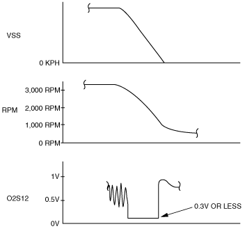
3. Drive the vehicle and decelerate the engine speed by releasing the accelerator pedal fully when the engine speed is 3,000 rpm or more.
4. Verify that the A/F sensor current (PID: O2S11) is 0.25 mA or more while decelerating as shown in the figure.
acxuuw00000099
• If not within the specification, inspect the A/F sensor for an open or short circuit. (See A/F Sensor Circuit Open/Short Inspection.) Then if there is no malfunction in the wiring harness, replace the A/F sensor.
A/F Sensor Heater Resistance Inspection
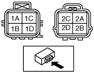
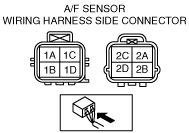
1. Disconnect the A/F sensor connector.
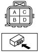
2. Measure the resistance between A/F sensor terminals 2B and 2D.
3. Inspect the following wiring harnesses for an open or short circuit. (Continuity inspection)
am3zzw00004698
acxuuw00000538
acxuuw00000103
Open circuit
• If there is no continuity in the following wiring harnesses, there is an open circuit. Repair or replace the wiring harness.
― A/F sensor terminal 1A and PCM terminal 2AD
― A/F sensor terminal 1B and PCM terminal 2AC
― A/F sensor terminal 1C and PCM terminal 2Z
― A/F sensor terminal 2A and PCM terminal 2M
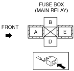
― A/F sensor terminal 2B and main relay terminal A
― A/F sensor terminal 2C and PCM terminal 2Y
― A/F sensor terminal 2D and PCM terminal 2C
Short circuit
• If there is continuity in the following wiring harnesses, there is a short circuit. Repair or replace the wiring harness.
― A/F sensor terminal 1A and body ground
― A/F sensor terminal 1A and power supply
― A/F sensor terminal 1B and body ground
― A/F sensor terminal 1B and power supply
― A/F sensor terminal 1C and body ground
― A/F sensor terminal 1C and power supply
― A/F sensor terminal 2A and power supply
― A/F sensor terminal 2B and body ground
― A/F sensor terminal 2C and body ground
― A/F sensor terminal 2C and power supply
― A/F sensor terminal 2D and body ground
― A/F sensor terminal 2D and power supply
HO2S Voltage Inspection
1. Warm up the engine to normal operating temperature.
2. Using the M-MDS, monitor the following:
― Vehicle speed (PID: VSS)
― Engine speed (PID: RPM)
― HO2S voltage (PID: O2S12)
3. Drive the vehicle and decelerate the engine speed by releasing the accelerator pedal fully when the engine speed is 3,000 rpm or more.
4. Verify that the HO2S outputs a voltage of 0.6 V or more, one time or more, then verify that the HO2S voltage (PID: O2S12) is 0.3 V or less while decelerating as shown in the figure.
acxuuw00000104
• If not within the specification, inspect the HO2S for an open or short circuit. (See HO2S Circuit Open/Short Inspection.) Then if there is no malfunction in the wiring harness, replace the HO2S.
HO2S Circuit Open/Short Inspection
aaxjjw00002474
acxuuw00000103
1. Disconnect the PCM connector.
2. Disconnect the HO2S connector.
3. Inspect the following wiring harnesses for an open or short circuit. (Continuity inspection)
Open circuit
• If there is no continuity, there is an open circuit. Repair or replace the wiring harness.
― HO2S terminal A and PCM terminal 2Q
― HO2S terminal B and PCM terminal 1BC
Short circuit
• If there is continuity, there is a short circuit. Repair or replace the wiring harness.
― HO2S terminal A and body ground
― HO2S terminal A and power supply
― HO2S terminal B and power supply
HO2S Heater Resistance Inspection
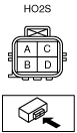
1. Disconnect the HO2S connector.
2. Measure the HO2S resistance between terminals C and D.
am3zzw00004699
• If not within the specification, replace the HO2S.
HO2S heater resistance
2—50 ohms
HO2S Circuit Open/Short Inspection (Heater)
am3zzw00004700
acxuuw00000103
1. Disconnect the PCM connector.
2. Disconnect the HO2S connector.
3. Inspect the following wiring harnesses for an open or short circuit. (Continuity check)
Open circuit
• If there is no continuity, there is an open circuit. Repair or replace the wiring harness.
― HO2S terminal C and ignition switch
― HO2S terminal D and PCM terminal 2D
Short circuit
• If there is no continuity, there is a short circuit. Repair or replace the wiring harness.